Optimizing throughput with Machine Vision Lighting

Within machine vision systems, inappropriate or poor quality lighting can often result in longer processing times and reduced throughput. However, by carefully selecting the optimum illuminator, you can ensure that defects are detected quickly and easily, increasing quality, reliability and yield.
It is always advisable that an optimum illumination study is conducted when setting up a vision system, and that it should be considered where images are not providing sufficient contrast – contrast being the ability to distinguish the difference between features of interest and the background. Ensuring that the light source is of a suitable brightness is critical as it can result in faster processing times, faster line speeds and higher quality products.
When optimizing your throughput, there are several factors that first need to be taken into account. These include the quality, speed, safety, cost and cost benefit – the foremost of which is quality.
Quality
Machine vision systems must perform their tasks accurately, and in most cases this means finding defects in the material under inspection, grading, sorting or measurement. The key to ensuring accuracy in a machine vision system is to obtain a good image. A suitable benchmark for this is an image that highlights the features of interest, allowing the system software to quickly and easily identify any issues, for example, a defect in the item under test. This is primarily achieved by enhancing the contrast between the features of interest, and the background.
Ensuring the quality of your throughput is essential, and is achieved by utilizing a high-quality machine vision lighting system. When selecting a system you must first consider the fundamentals of wavelength, angle of illumination and uniformity of the lighting system.
Wavelength
Selecting the correct wavelength can mean the difference between a high- and a low-quality vision system. It is important that all sections of the spectrum are considered, in terms of both visible and non-visible light, as the spectral response of camera systems differ. By using high power illuminators, which are available from ultraviolet through visible to infrared wavelengths, machine vision system designers can optimize contrast without compromising image brightness or sensitivity.
White light sources with filters have typically been used in older systems to improve the overall contrast of the system, but as most of the light is unused, this leads to a reduction in intensity. Well-chosen monochrome illumination offers higher efficiency and brightness, whilst achieving the same contrast. Designers have more scope to enhance contrast when light is delivered at a discrete wavelength (as in LED systems).
As an alternative to visible light, infra-red illumination can diminish color effects in monochrome images. This not only simplifies inspections, but also reduces the need for complex processing of the image. Ultra violet (UV) light sits below the violet end of the visible spectrum. In UV applications like food sorting and currency inspection, UV illuminators with their shorter wavelengths can be used to highlight UV fluorescent inks or materials.
Angle of Illumination
In order to optimize throughput, it’s critical that the correct angle of illumination be selected for your given application as the shape, surface structure and material of the objects in question will all influence the way the light is reflected. Front lighting and back lighting are the most common techniques used and these are defined below.
Figure 1: Front lighting system in inspection application
Front lighting is where the camera and the light source are on the same side of the target; see Figure 1. Within this, bright-field illumination is categorized by light from the target being uniformly reflected into the camera. This technique is most commonly used where the target reflects the light in a diffuse way; see Figure 2 (a). Dark-field illumination describes applications where the majority of light is reflected away from the camera, making it ideally suited for use on highly reflective materials such as glass or films; see Figure 2 (b).
In backlighting systems, the camera and illuminator are on opposite sides of the target; see Figure 3. Applications range from detecting small perforations in a substrate to qualitative measurements of opacity as the camera views the light directly through the target material.
Figure 2(a): Diffuse Reflection Figure 2(b): Specular Reflection
Figure 3: Backlighting System Uniformity
A uniform and intense light source is extremely important in machine vision systems. If the light source is not uniform, it is more difficult for the system software to identify defects in the target material, as the non-uniform light results in noise, leading to an unclear signal to the system. For example, any edge will show-up on camera as a much brighter spot than a flat surface as a result of non-uniform reflections. In a system where the light is non-uniform, it becomes more difficult for the camera to distinguish between actual edges, defects, etc. or bright spots as a result on the non-uniform illumination itself. A uniform and intense light source will result in a clearer image.
Speed and Reliability
There are four main factors that influence production line speed and reliability in relation to lighting systems. They are: light technology, processing time, downtime, and changeover time.
Light Technology
When considering a LED light for your vision system, it is important to be aware that there can be significant differences in the output, expected lifetime and performance. The illuminator performance in particular depends on how well the illuminators are designed and manufactured. ProPhotonix engineers select the optimum packaging technology to achieve the required performance. Most of our products are designed using Chip-on-Board (COB) technologies, and because COB technology allows for a much higher packing density than surface mount technology, the resulting higher intensity means that systems can be run at higher speeds. Essentially, more photons results in faster image capture; reduced processing times.
Fig. 4: LED Packaging Methods
Because the product on production lines is moving, there are three solutions to ensure a good image is obtained. The first option is to stop the product. In some cases this is not appropriate. The second option is to strobe the light source and as such freeze the motion. Strobing can be an extremely useful tool. If used correctly, it can offer increased intensity and longer illuminator lifetimes; however, if used incorrectly it can result in failure of the light or reduced lifetime. The third option is to utilize a line scan system which will take a continuous image of the production line.
Line scan cameras have a linear array of sensors as opposed to a two-dimensional (2D) matrix found in area scan cameras. When a target object is in motion, the system’s 1D camera obtains a 2D image by building it up line by line. The density of pixels across the 1D sensor, and the line rate at which the camera runs, means that line scan cameras can provide very high resolution images, provided sufficient light is available. Line scan vision systems are ideally suited to inspections at higher speeds; however, the trade-off is that a greater demand is placed on the light due to the short exposure times.
Processing Time
When a vision system analyses images captured by a machine vision camera, the analysis is set to measure parameters or detect defects. The effectiveness of the vision system needs to be optimized to grade material or prevent material that is not fit for purpose from being further processed. It is vital to ensure that the software can distinguish a clear signal in the captured image; however, it is difficult for the system to extract useful information about the test media if the features of interest are not distinctive in the image. The solution is to enhance the contrast, resulting in faster processing times.
Downtime
LED-based light sources offer many advantages over traditional light sources. Typical lifetimes, for example, are in excess of 50,000 hours – an equivalent of more than five years of continuous operation which greatly reduces the need to replace failed lamps. This in turn lowers maintenance costs and reduces line downtime. Not all LED systems are the same, however, the product design is critical to maximize the capabilities offered by LED Technology. Good thermal management is key to ensuring this, and the ability to control the intensity of the LEDs can further extend the lifetime.
Changeover Time
Flexible lighting sources, such as those offered by ProPhotonix, can offer significant advantages over traditional light sources especially in the area of changeover time. For example, where different products need to be inspected on the same production line, traditional light sources or non-optimized LED light sources may require a new light source with each product change, or for changes to an optical filter. In well-designed products, each LED chip can be individually controlled creating a much more flexible light source that allows the emission wavelength and/or intensity to be altered to suit the product being inspected. This reduces both line downtime and set up time resulting in an increase in productivity.
Safety
All applications require that safety features be included in the designs. For example, in ANPR/ ALPR applications, the key safety consideration is eye safety. In this application, the trade-off is to select a wavelength that optimizes camera sensitivity but that takes into account the sensitivity of the human eye, thus ensuring that road users are not impacted by the system.
Intensity will always need to be managed to ensure the safety of users and in the majority of machine vision applications, the relative intensity of the light is very high. ProPhotonix considers all safety options involved and recommends that eye protection be worn as a precaution, where appropriate.
Protection features can also be incorporated into the light using a combination of electronics, optics and software to prevent the host system from accidentally overdriving the Illuminator, thereby preventing catastrophic failure.
Product safety precautions have been built into ProPhotonix’s designs. Where necessary constant thermal monitoring of the substrate temperatures have been included, in addition to completely software controlled flagged alarms and safe shutdown procedures.
Cost
Utilization of machine vision systems should result in reduced costs, the elimination of subjective judgment, and allow productions lines to run free of fatigue. When designing a machine vision system, it is important that the best solution should take into account not only the up-front costs of the system, but also the lifetime costs in comparison to alternative solutions, as well as the measured impact on the business or research.
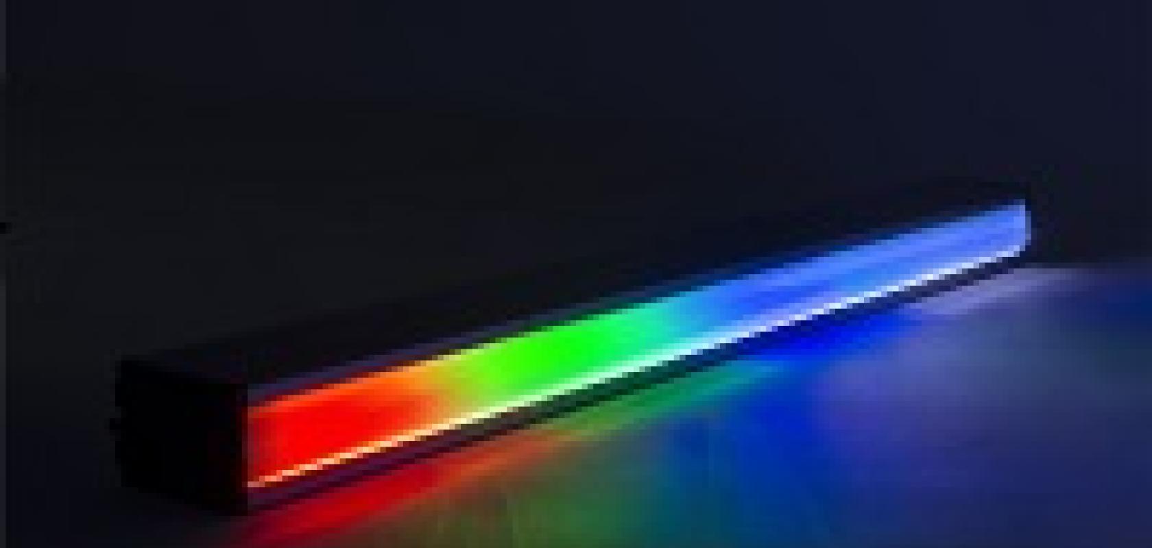
Fig. 5 Multi-Wavelength Solution from ProPhotonix
Customers often engage with an LED lighting company towards the end of a design process. By engaging early, you have the freedom to choose from a wide variety of lighting solutions, form factors and specifications before the final design is too constrained. Engaging early can save time and money and reduce the development time of the imaging system. Indeed, with the proper choice of illumination developed at the onset of a machine vision system project, designers may find that expensive hardware and software costs in the system can be reduced.
Conclusion
It’s important to consider machine vision lighting early in the procurement process, and due to the nature and complexity of the applications involved, you may find that an off-the-shelf lighting solution cannot provide the dynamic range or intensity required to run your production line at a sufficient speed. A high-performance, customized lighting system, such as those supplied by ProPhotonix, could therefore be necessary. While custom solutions can have higher up-front costs, the productivity gains will more than offset this expense.
Need more information on Machine Vision Lighting?
Download our Machine Vision Lighting Brochure here.

